
Forklift Sensor Identification & Selection Guide
Identify what the sensor measures, which controller receives its signal and how it mounts. Thread size, connector shape and pin count alone do not establish an interchangeable sensor.
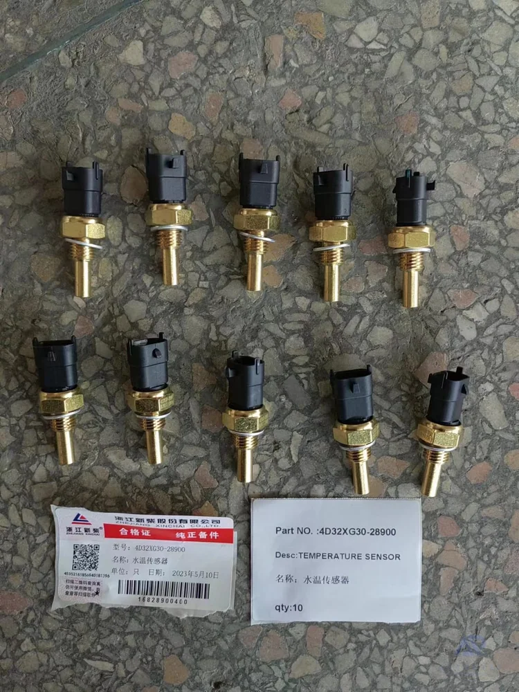
4D32XG30-28900 coolant-temperature sensor reference. Confirm the thread, connector and signal characteristic before selecting a replacement.
Identify the function before the reference
| Sensor function | Signal / operating information | Physical interface and receiving system |
|---|---|---|
| Speed | Technology, pulse pattern, direction channels, target and air gap | Shaft/wheel/transmission position; controller input |
| Crankshaft / camshaft | Hall or inductive design, timing/target relationship | Mounting, insertion length and engine ECU |
| Coolant / oil / motor temperature | Range and resistance curve or active signal | Probe, thread/seal and receiver specification |
| Hydraulic / oil pressure | Pressure range/reference, supply and output | Pressure port, sealing seat and controller input |
| Accelerator position | Supply, channels and rest/full-travel signal | Pedal assembly and traction controller / engine ECU |
| Steering angle | Range, zero reference and signal channels | Steering linkage/coupling and receiver configuration |
| Proximity / position | Sensing distance, flush/non-flush, NO/NC and PNP/NPN where applicable | Target, mounting and interlock/position input |
| Load | Force direction, capacity, excitation and output | Mechanical load path and load-monitoring system |
| Battery temperature | Temperature characteristic and BMS input | Probe, harness and exact battery/BMS configuration |
Manufacturer examples explain why small details matter
HELLA position sensing
Position-sensor families can use analog, PWM or other digital interfaces. Hall and inductive crankshaft sensors may look similar; pin count is not a definitive technology test. Passenger-car test values are not forklift specifications.
ifm hydraulic pressure and proximity
4–20 mA and 0–10 V are possible output signals, not supply-voltage descriptions. A mounting thread and an electrical connector can both be called M12 while describing different interfaces.
A switch is not a proportional position sensor
A dead-man foot switch confirms an operating condition. An accelerator-position sensor reports pedal movement. Do not interchange them because both are pedal-shaped. Identify the function before comparing the housing or connector.
Send the old-part label and a photo showing where the pedal or sensor is fitted; include the controller or ECU model if you have it.
Matching the same thread is not enough
Start with the measured function and sensing characteristic, then compare the supply, output, mounting and connector. The final check is whether the receiving controller, ECU or BMS expects that exact signal, range and channel arrangement, including calibration or zero-position requirements where applicable. Neither a matching thread nor an existing fault code settles that relationship.
| Looks similar | Difference that matters |
|---|---|
| Same plug and pin count | Supply, pin allocation, signal type or number of channels |
| Same pressure-sensor body | Range, output and sealing seat |
| Same temperature-sensor thread | Resistance curve, probe length or active interface |
| Same proximity-sensor housing | PNP/NPN, NO/NC, sensing distance and mounting mode |
| Same pedal or angular housing | Signal calibration, travel, zero position or safety-switch function |
Send the location and label first
Tell us what the sensor measures or where it is fitted. Add a readable label, truck model/serial and connector/mounting photos. Controller, ECU or BMS identity helps when known. Existing fault codes can be included, but a code alone does not identify the replacement.
Do not remove a sensor from a pressurized circuit, dismantle a brake system or open an energized battery to collect inquiry information. Drawings or qualified-service measurements are preferable.
Ask about the part you need
A part number is optional. Send it if you have it, or choose the identification route that fits your information. No technical field below is required.
Related parts and selection information
Technical references
Manufacturer examples are not confirmed Authpart stock or vehicle fitment. Check the current documentation for the exact model and revision.
More help choosing the correct part
Forklift EPS Controller Selection: Motor, Sensor and CAN Interfaces · Forklift Solenoid Valve and Coil Selection: Voltage, Bore and Valve Function · Forklift Steering Knuckle Identification: Side, Kingpin and Hub Interfaces · Forklift transmission components: identify the assembly and repair part · Forklift seat suspension and safety-switch options · Forklift light and warning-device specifications · Forklift connectors and plugs: power, signal and mechanical keying